Orb: Introduction
27 Mar 2012[ part of the orb series ]
The original Orb was a simple thing; a BlinkM on the end of a long piece of telephone cable plugged into an Arduino, controlled by the low-powered Linux server behind my TV that’s always on.

That isn’t the sort of simplicity that makes it suitable for everyone. Putting aside how the behaviour of the Orb is configured, the physical design had two drawbacks:
- the need for an always-on PC and
- having the Orb physically tethered to the PC
These were key to the new design.
The always-on PC can be replaced with an Arduino Ethernet, connecting to an on-line service for configuration. This puts the base unit within cable reach of the broadband router - but unlikely to be near the ideal spot for the Orb to sit. So the cable between the Orb and Arduino can be replaced with a wireless link. It will still need a power supply, but that’s more likely to be available wherever the Orb ends up.
This has the knock-on effect of requiring more than just a BlinkM, or equivalent, in the Orb; it needs an Arduino in the base. Looking at the available boards, the only potential one that might fit is the LilyPad - but even that is a bit large and doesn’t quite lend itself to the form factor I have in mind. This means it needs a custom board.
With regard the BlinkM, I have already prototyped a custom LED board to achieve multiple channels. That needs shrinking down further to a single board.

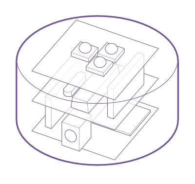
This brings me to the basic design of the new Orb. It consists of three boards that stack together - much like an Arduino and its shields. The top board holds three RGB LEDs and the resistors they need. The middle board includes the basic Arduino circuit, consisting of a micro-controller and the bits needed to make it tick, as well as a programming header. Finally, the bottom board has the main power connector and associated components along with a radio transceiver.
All within the base of an Orb.
Over the next couple of posts, I’ll write more about the boards themselves. They were the first PCBs I’ve designed in Eagle and taken all the way through to getting fabricated.