Orb: The Bottom Board
01 Aug 2012[ part of the orb series ]
 With the Orb needing to be wireless, one of the early decisions was what sort of wireless to use.
The first option to consider was Wi-Fi. This would allow the Orb to connect straight to the Internet via the home router - no intermediary is needed. The downside is that the Orb doesn’t have any sort of UI that would allow configuration of the Wi-Fi settings. Some Arduino WiFi shields will read the configuration from an SD card - but that is not at all a nice user experience. Nor is there a lot of space available on the bottom board to fit all of the hardware in. It is also an expensive option. Likewise Bluetooth and ZigBee weren’t really a good fit.
That left a 433Mhz, or similar, radio link. I had played around with some cheap radio transceivers before and they seemed a good way to go. But then I discovered the RFM12B module via JeeLabs. Jean-Claude has written a lot about the module on his blog and has created an Arduino library for driving it - perfect for the Orb. Another benefit is that the Nanode board comes with this module - making it nicely interoperable.
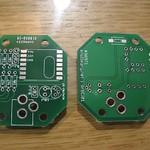
The downside of the module is that it runs at 3.3V - but the rest of the Orb runs at 5V. I considered squeezing in the appropriate voltage regulators to provide both voltages from an unregulated supply. But I decided it would be easier to offload some of that by requiring a regulated 5V power supply. That way, the bottom board only needs a regulator to provide 3.3V to the radio, as well as a set of voltage dividers on each of the signal lines between the radio and the ATmega328. It also opens the option of using a micro-USB port as has become standard with mobile phone chargers - although that’s for the future.
Although I said the Orb has no configuration interface, I decided it needed something. A common pattern with radio-linked devices, such as the CurrentCost meters, is that you press and hold a switch to put the device into a pairing-mode. This mode allows you to not only establish a link between the device and a base station, but also to link multiple devices with a single base, whilst maintaining their individual addressability. To this end, I included a surface-mount switch on the underside of this board so it can be accessed through the bottom of the Orb housing.
As ever, the schematics are on github.
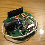
And that’s the final board. All soldered, stacked and ready to do its thing. What’s next? Making a base to house these boards in. But that’s for another day.