Orb: The Base
23 Aug 2012[ part of the orb series ]
 The base of my original Orb was cut out of a thick piece of wood using a circle cutting drill bit. A pair of slightly smaller circular bits were then used to create a recess in the top of the base and finally a hole drilled through the centre. This was all it needed to glue the BlinkM in place with the lead running out of the base to the off-board arduino.
This approach wasn’t going to work for the new Orb, which needs a hollow base to house all of the boards. It also needed to be something that others could easily replicate.
I discounted 3D printing early on, as I wanted the base to be wooden. This left some sort of laser cut thing. There are a number of on-line services for getting things laser cut, such as Ponoko. They offer a wide range of materials, including 3mm thick plywood - ideal for this.
To figure out what that base was going to look like, I started by glueing a stack of cardboard together and literally carved out the shape I wanted. This let me work out what each of the individual 3mm layers needed to look like. It also helped to identify how to make the base in such a way as to allow the PCB to be accessed; I didn’t want it to be a permanently sealed unit.
The base consists of 12 layers, with 3 in the bottom ‘half’ and 9 in the top (the diagram over on the left omits most of the layers). A pair of nuts, shown in red on the diagram, are sandwiched between layers in the top half, which allow the two sections to be held together using screws. The bottom of the base also includes holes for mounting the PCB stack to it.
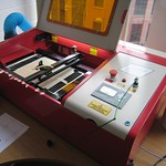
With the layers drawn up in inkscape, it was time to get them made. A chance conversation with Adrian McEwen at a #iotlondon meetup enabled me to take advantage of DoES Liverpool’s laser cutter.
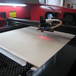
Adrian kindly took some photos of the LASER in action.
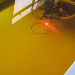
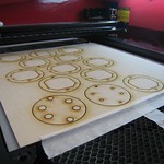
Proving yet again, atoms are hard, this first pass wasn’t a complete success. I had made the space in the centre of the base layers the exact same size as the PCBs - so exact that the PCBs didn’t quite fit. A quick rework of the design and another pass with the lasers and I had all the bits I needed.
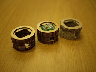
Some glueing and sanding later, and the base looks quite good - although I don’t appear to have a more recent photo of it to hand. It needs some more work as the design didn’t properly take into account how the orb actually attaches to the base - I have vague thoughts about the liberal use of a hot-glue gun to achieve this currently. I’ve also had some thoughts about changing the style of power-supply connector, which will change the size of opening needed in the side.
But all in all, a significant step forward as it now looks more like something people would be prepared to have sat in their home.